
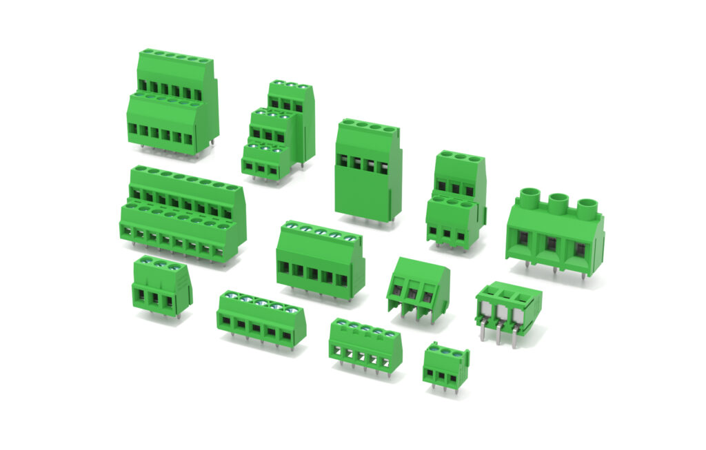
What Is a PCB Terminal Block?
A PCB terminal block (also called a PCB connector or board-mounted terminal) is the wiring interface soldered directly onto a printed circuit board — the point where external wires meet the circuit. Every power supply, PLC module, inverter, HVAC controller and instrument panel uses them, because a reliable board-to-wire connection is what makes the whole product serviceable.
Choosing the wrong type means rework at best — and failed vibration tests, loose wires or overheating at worst. This guide walks through the four connection types, the pitch system, pin orientation, materials and a practical selection checklist, from the perspective of a PCB terminal block manufacturer.
The Four Connection Types at a Glance
| Type | Connection Method | Best For | Rework / Service | Our Product |
|---|---|---|---|---|
| Screw type | Screw clamp, screwdriver tightening | Maximum wire compatibility, proven reliability | Re-tightenable | Screw Type PCB Terminal Block |
| Pluggable | Female socket on PCB + male header plug | Modules that must be detached for service | Plug / unplug in seconds | Pluggable PCB Terminal |
| Push-in (screwless) | Spring clamp, direct wire insertion | Fast assembly, vibration environments | Tool-free release | Push-In PCB Connector |
| Barrier type | Isolated barriers between poles, screw | High current, panel mount, safety isolation | Re-tightenable | Barrier Terminal Block |
Screw-Type PCB Terminal Blocks
The classic and still the most widely specified. A brass screw clamps the conductor with high, re-tightenable contact force — it accepts nearly any wire type and cross-section, tolerates imperfect strips, and gives a visible, inspectable connection. Available in straight pin for standard boards and right-angle pin versions where wires must exit parallel to the board in low-profile enclosures. Typical homes: power supplies, instruments, industrial controllers.
Deep dive: Screw Type PCB Terminal Block — structure, materials and applications.
Pluggable PCB Terminal Blocks (Female Socket + Male Header)
A two-part system: the female socket solders onto the PCB, and wires terminate into a mating male header plug. The payoff is serviceability — a module can be unplugged, tested or replaced without touching a single solder joint or wire. That is why pluggables dominate PLC I/O cards, drive controllers and any field-replaceable module.
For new designs, specify both halves from one source to guarantee mating geometry and locking fit. See our PCB mount female sockets and plug-in male headers, or the full overview: Plug-in PCB Terminal Block guide.
Push-In (Screwless) PCB Terminal Blocks
An internal stainless spring grips the conductor the moment it is pushed in — no screwdriver, no torque spec, no loosening over time. Vibration resistance is excellent because the spring constantly compensates. Assembly time drops sharply on high-volume production lines. The trade-off: wire range is narrower than screw types, and very fine stranded wires may need ferrules. Ideal for power supplies, instrumentation and automation equipment produced in volume. See Push-In Quick Terminal Block and the tool-free quick terminal series.
Barrier Terminal Blocks (Panel Mount)
Barrier blocks put an isolation wall between adjacent poles — preventing arcing and short circuits in high-current, high-voltage wiring. They mount to panels and enclosures (not only PCBs), handle large cable cross-sections, and their open construction makes inspection easy. Typical applications: distribution boxes, home appliances, power supplies. For a structured comparison with standard PCB blocks, see PCB Terminal Block vs Barrier Terminal Block: Which to Choose.
Specialized: Transformer Terminal Blocks
Low-voltage transformers, regulators and distribution equipment have their own terminal geometry — panel or through-hole mounting with reinforced clamping for transformer leads. If you are sourcing specifically for transformer manufacturing, see our Transformer Terminal Block page.
Pitch: The Dimension That Decides Everything
Pitch — the center-to-center distance between poles — is the first parameter to lock down, because it fixes your PCB footprint. The industry-standard families:
| Pitch | Equivalent | Typical Role |
|---|---|---|
| 3.5 / 3.81 mm | — | Dense signal wiring, compact boards |
| 5.0 / 5.08 mm | 200 mil | The universal workhorse for power and signal |
| 7.5 / 7.62 mm | 300 mil | Higher current power circuits |
Two rules of thumb: current capability rises with pitch (roughly 8–10 A class at 3.5 mm, mid-teens at 5.08 mm, ~20–30 A class at 7.62 mm — always confirm against the datasheet), and once a pitch is laid out on the board, replacements must match it exactly. We supply the full pitch range — ask for the pitch & pole-count matrix.
Materials & Safety Standards
- Conductor: high-conductivity brass, nickel or tin plated for corrosion resistance and solderability
- Housing: PA66 nylon, UL94 V-0 flame retardant — self-extinguishing, high CTI, stable from −40 °C to +105 °C
- Certifications to look for: UL (North America), CE (EU), RoHS, TÜV — our PCB terminal blocks carry these per product line; certificates available on request
Selection Checklist
- Pitch — matches the PCB footprint exactly (3.5 / 5.0 / 5.08 / 7.62 mm families)
- Pole count — from 2P to 24P; longer rows may need a jumper system for commoning
- Current & voltage rating — under your worst-case ambient, not just nameplate
- Wire range — verify both minimum and maximum cross-section, AWG and mm²
- Pin orientation — straight or right angle, per enclosure height
- Service model — will the module ever be removed? If yes, pluggable
- Environment — vibration pushes toward push-in springs; re-torque access pushes toward screws
Frequently Asked Questions
Screw or push-in — which is more reliable?
Both are proven. Screws win on wire flexibility and repairability; push-in springs win on vibration and assembly speed. For volume production with controlled wire types, push-in is usually faster and immune to under-torquing.
Can I mix terminal types on one board?
Yes — many designs combine pluggable connectors on serviceable modules with screw or push-in blocks for fixed wiring. Just keep pitches aligned per row.
Do you supply both halves of pluggable systems?
Yes — female PCB sockets and mating male header plugs, specified as a pair so the locking fit is guaranteed. Contact us with your pitch and pole count.
Spec Up Your Next Board
Send us your pitch, pole count, wire range and current requirement — we will return the matching models, datasheets and a quotation, usually within one business day. Request PCB terminal block specs here.