
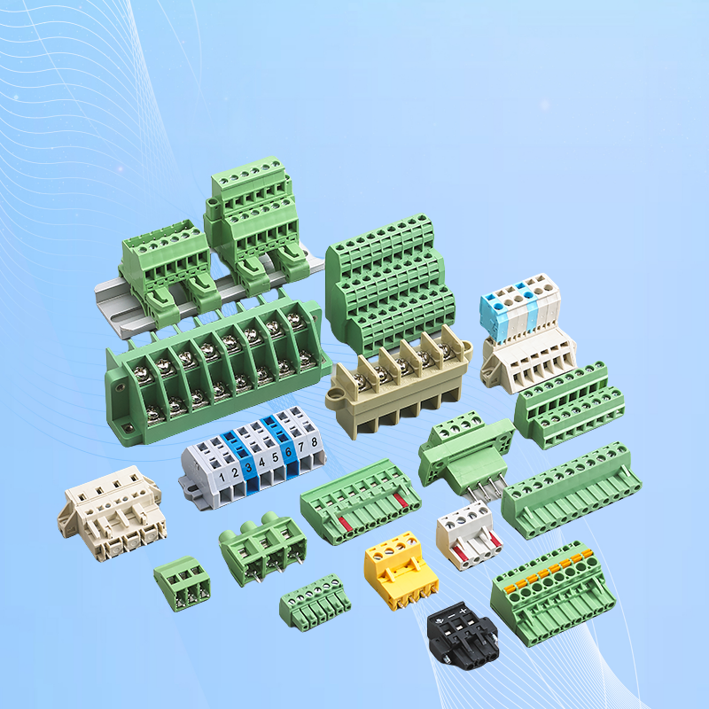
PCB Terminal Block vs Barrier Terminal Block: Which to Choose
When you design a PCB or wire a control panel, one of the first choices is the terminal block style. PCB terminal blocks and barrier terminal blocks look different, mount differently, and suit different applications. This guide helps you pick the right one.
What Is a PCB Terminal Block?
A PCB terminal block mounts directly onto a printed circuit board (PCB). Solder pins or through-hole terminals let you connect external wires to board-level circuits without soldering wires directly to the PCB — which makes assembly, maintenance and field replacement much easier.
Common pitch options include 2.54 mm, 3.5 mm, 5.0 mm, 5.08 mm, 7.5 mm, and 10.0 mm. Current ratings typically range from a few amps for signal up to 30 A or more for power versions.
Use a PCB terminal block when your connection point is on a circuit board — such as power entry, I/O interfaces, sensor connections, or driver modules.
What Is a Barrier Terminal Block?
A barrier terminal block (also called a barrier strip) is a screw-terminal block with physical barriers between each pole. It is usually chassis-mounted or DIN-rail mounted, not soldered to a PCB. The barriers prevent accidental contact between adjacent terminals, making it safer for higher voltage and current applications.
Barrier strips are common in industrial control panels, power distribution units, HVAC equipment, and anywhere you need robust, field-serviceable connections with clear separation between circuits.
Key Differences at a Glance
Mounting: PCB blocks solder onto a circuit board. Barrier blocks bolt onto a chassis or snap onto a DIN rail.
Wire access: PCB blocks are compact and close to the board. Barrier blocks give you more room to work with larger-gauge wire.
Current capacity: Barrier blocks generally handle higher currents (often 20–60 A+). PCB blocks cover low-to-mid range (typically under 30 A).
Safety: Barrier blocks have physical dividers between poles. PCB blocks rely on pitch spacing and PCB layout for isolation.
Serviceability: Barrier blocks are easy to rewire in the field. PCB blocks require desoldering or a connector.
When to Choose a PCB Terminal Block
Your connection is on a PCB (power input, I/O, sensors).
You need compact size and light weight.
Pitch-matched to your PCB footprint (e.g., 5.0 mm, 5.08 mm).
Lower to medium current (up to ~25–30 A).
Examples: our KF300/DG300 series screw PCB terminal blocks, CH1/CH2/CH3 push-in quick terminal blocks, and 262/260 series cage clamp terminal blocks.
When to Choose a Barrier Terminal Block
Chassis or DIN-rail mounting (not on a PCB).
Higher current and voltage (power distribution, motor feeds).
Field wiring that changes over time.
Applications where safety inspectors require visible isolation between poles.
Examples: our UUK series power distribution terminal blocks, TBC series DIN rail double screw terminal blocks, and URTK-S test disconnect CT terminal blocks.
Quick Decision Guide
Connection on a PCB? Use a PCB terminal block.
DIN rail or chassis mount, high current? Use a barrier terminal block.
Need field re-wiring? Barrier block.
Compact, board-level integration? PCB block.
Not sure which fits? Contact us with your application details — we will recommend the best match for your design.
Related Products
- Screw Type PCB Terminal Block — board-level screw connection, straight and right-angle pins.
- Barrier Type Terminal Block — isolated, high-current panel connection for distribution and appliance wiring.
- PCB Terminal Block Types: Complete Selection Guide — the full four-type comparison in one place.
Download the Complete Catalog
All pitch options, current ratings, wire ranges and ordering codes in one printable PDF: get the free GS series catalog here.